Submitted by guitar-list on
Project:
Step number:
Instructions:
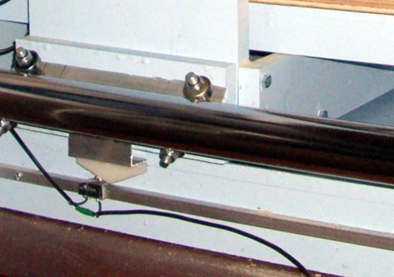
HEALTH WARNING - THE LIMIT SWITCHES IN THE PICTURES ARE MOUNTED BACKWARDS - they would be safer facing the other way. Photos will be changed ASAP.
The limit switches are microswitches which signal when the machine has reached its limits of travel. The controlling program will then stop the machine to prevent damage.
Home switches are used to zero the machine to a known reference point. Due to the limited number of input pins on a standard parallel port I am using the negative limit switches on the X and Y axes as home switches, and the positive limit switch on the Z axis as a home switch. Using a PCI parallel port card would allow you to have the full 9 switches (6 limits and 3 home), but sharing the limits and home is sufficient for this machine.
I have mounted the limit switches on U shaped aluminium profile which fits snugly over square aluminium tube. The switches can slide up and down the tube and are kept in place with a set screw. I thought that some adjustment might be useful, to stop the machine running into hold-down clamps etc.
The switches are triggered by HDPE ramps (made from cutting board) mounted on the alumiunium angle left over from making the linear bearings.
The switches are wired in series for each axis and are normally closed. The breakout board has pull down resistors to prevent noise from entering the circuit when the switches are open.


